Instrucciones de instalación de Schluter®-KERDI-SHOWER-FRS

Descargue las instrucciones de instalación de Schluter® -KERDI-SHOWER-FRS.

Descargue la tabla de grosores de los componentes Schluter® -KERDI-SHOWER-FRS.

Descargue el diagrama de colocación de soportes Schluter® -KERDI-SHOWER-FRS.


PLANIFICACIÓN
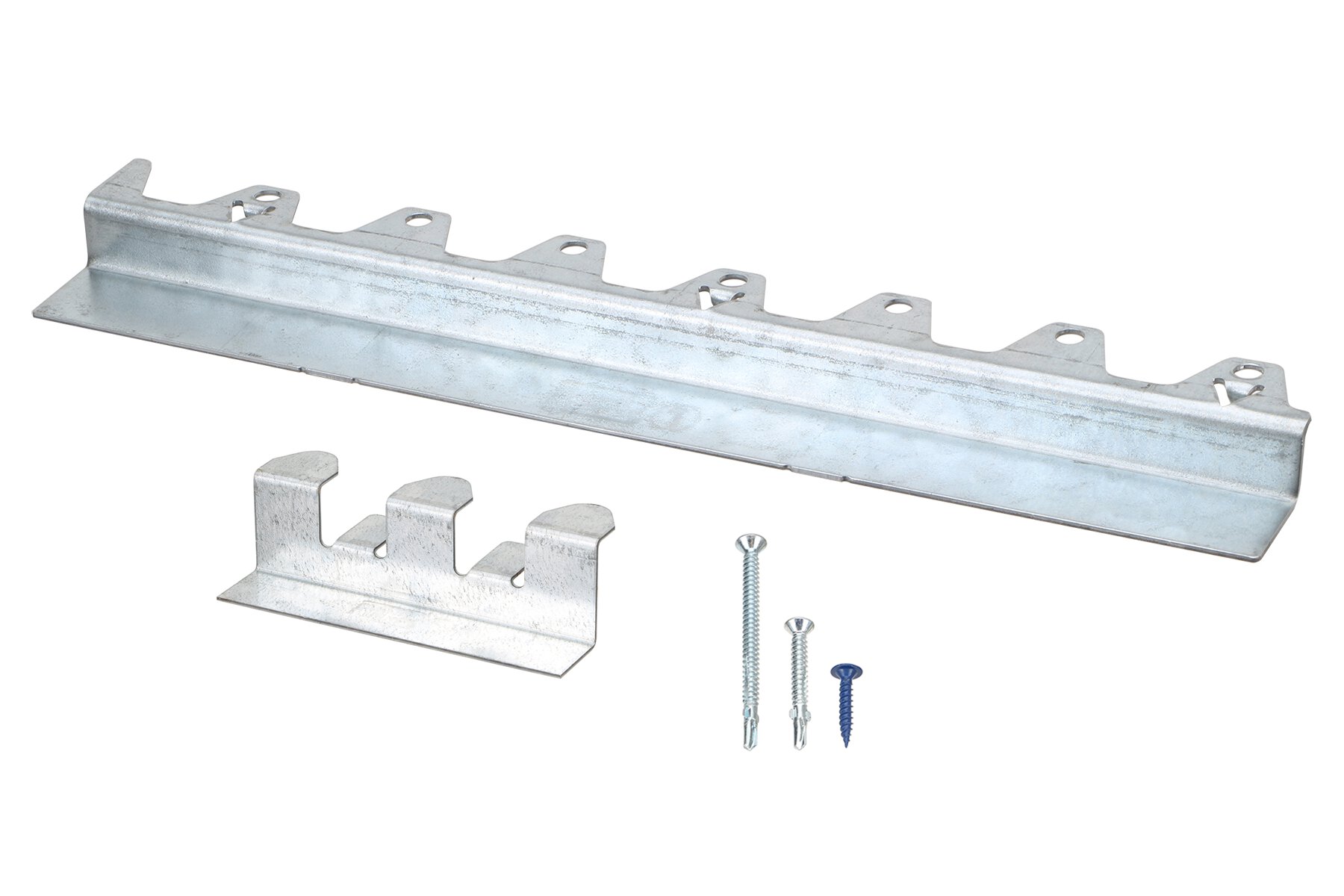
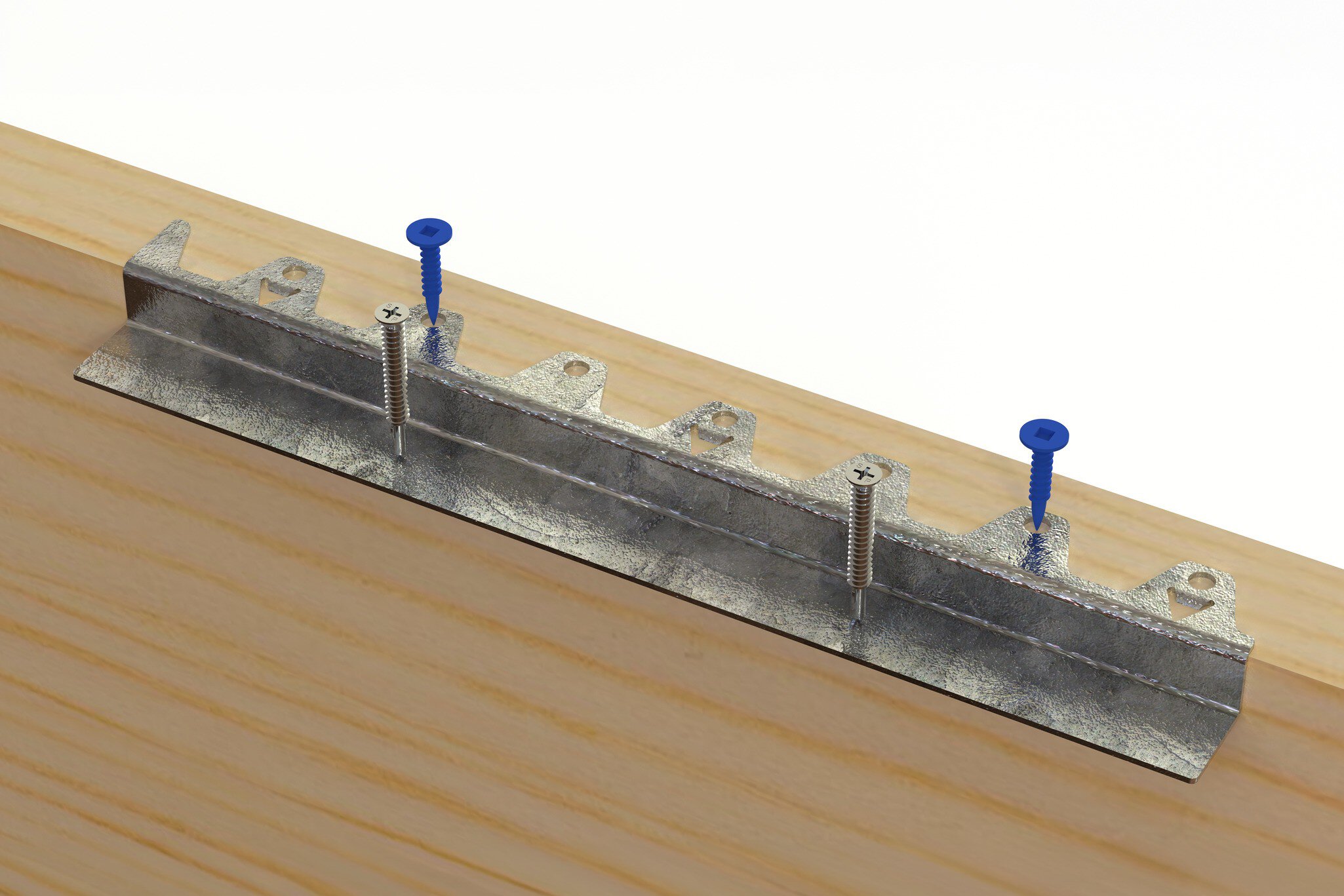
Schluter Systems KERDI-SHOWER-FRS galvanized steel brackets and mounting screws for curbless shower framing Schluter Systems KERDI-SHOWER-FRS galvanized steel brackets and mounting screws for curbless shower framing Schluter Systems KERDI-SHOWER-FRS galvanized steel brackets and mounting screws for curbless shower framing
1. Compruebe que el espaciado entre vigas no supere las 19.2” (49 cm) desde los centros.
2. Las instalaciones sobre un substrato de 5/8" (16 mm) requieren el uso de las calzas Schluter®-KERDI-SHOWER-FRS (n.º de artículo: KS FRS SH60).
3. *La perforación previa para tornillos de madera a metal de 1 5/8" y 2 3/4" puede acelerar y facilitar la instalación. Utilice una broca de 1/8" (3.2 mm) con tornillos n.º 10.
4. Prepare la madera contrachapada de 3/4" (2 cm) requerida para los insertos FRS. La madera contrachapada debe cumplir los requerimientos del código de construcción local para substratos.
5. Obtenga los materiales para las piezas de relleno. Puede utilizar madera contrachapada u OBS.
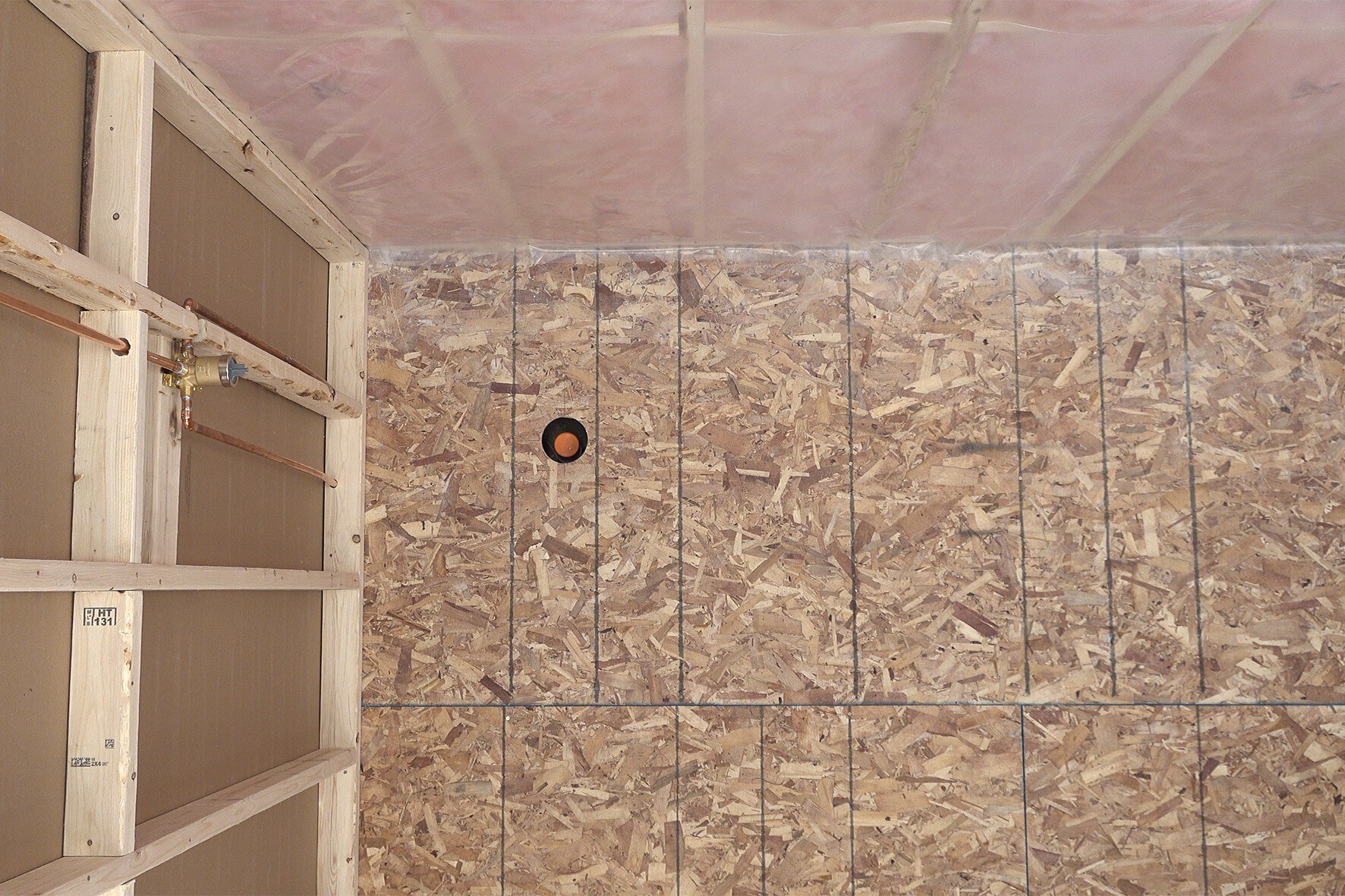
6. Compruebe que la profundidad de la cavidad del piso tras el rebaje de 11/16" (17.5 mm) sea suficiente para albergar todos los componentes de plomería.
7. Utilice únicamente los fijadores suministrados para los soportes y los insertos.
8. El canto del panel y la membrana deben quedar a ras. Utilice la TABLA DE GROSORES DE LOS COMPONENTES para planificar adecuadamente. Se recomienda utilizar el sistema FRS con los paneles Schluter®-KERDI-SHOWER-TT debido a su perímetro delgado.
9. Consulte la GUÍA DE SELECCIÓN DE KITS DE FRS Y KITS DE SOPORTES que figura a continuación para obtener orientación sobre cómo elegir los kits en función del tamaño y las condiciones de su instalación.
Si el piso presenta un bloqueo considerable, es posible que se requieran soportes adicionales.

Consideraciones especiales para duchas sin rebordes

Consulte los códigos locales para determinar si se requiere un sistema de drenaje secundario. Se puede utilizar Schluter®-KERDI-DRAIN-F.
Tenga en cuenta la dirección del agua de la ducha y la ubicación de la cortina o la mampara. El agua rociada hacia la base de una barrera o mampara puede salir de la zona de la ducha; planifique la ubicación de los accesorios en consecuencia.
Las duchas sin rebordes recubiertas con baldosas dependen de la pendiente del piso para retener eficazmente el agua en la zona de la ducha y dirigirla hacia el desagüe.
La gestión proactiva de las obstrucciones en los desagües reviste especial importancia en las instalaciones de duchas sin rebordes; asegúrese de informar debidamente al usuario final.
Diversas normativas de construcción y otras fuentes, como la Ley para Estadounidenses con Discapacidades (ADA), incluyen requerimientos específicos en materia de accesibilidad para personas con discapacidades, por lo que deben consultarse cuando proceda.

INSTALACIÓN

1

Haga un orificio en la parte inferior de la pared para fijar el soporte en P, retirando una sección de yeso suficientemente grande como para que quepan por el orificio el taladro, los tornillos y sus manos.

2

Trace el contorno del panel en el piso, teniendo en cuenta el grosor de los paneles de yeso y añadiendo 1/8" (3.2 mm) de espacio adicional por todos los lados para compensar el grosor de los soportes y las imperfecciones del corte.


3

Recorte la sección trazada.

Ajuste la profundidad de corte adecuada y tenga cuidado de no dañar las vigas.
Utilice una herramienta de corte al ras u oscilante para cortar lo más al ras posible a lo largo de la placa inferior de la pared.
4

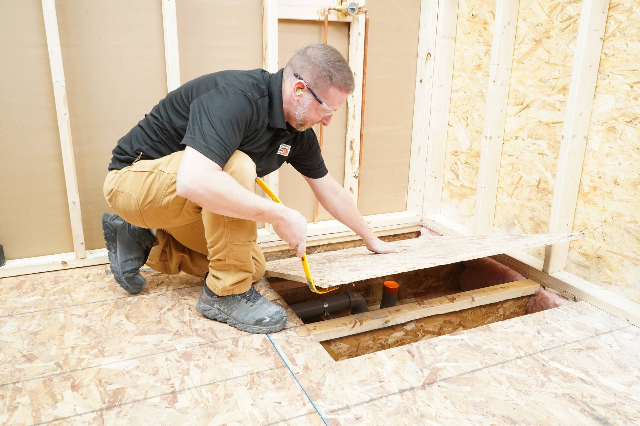
Retire todos los fijadores del substrato a los que pueda acceder y, a continuación, levante las secciones recortadas con las herramientas adecuadas. Tenga cuidado de no dañar las vigas ni el substrato restante, ya que pueden quedar restos de pegamento y fijadores.

Precaución: No pise entre las vigas.
5

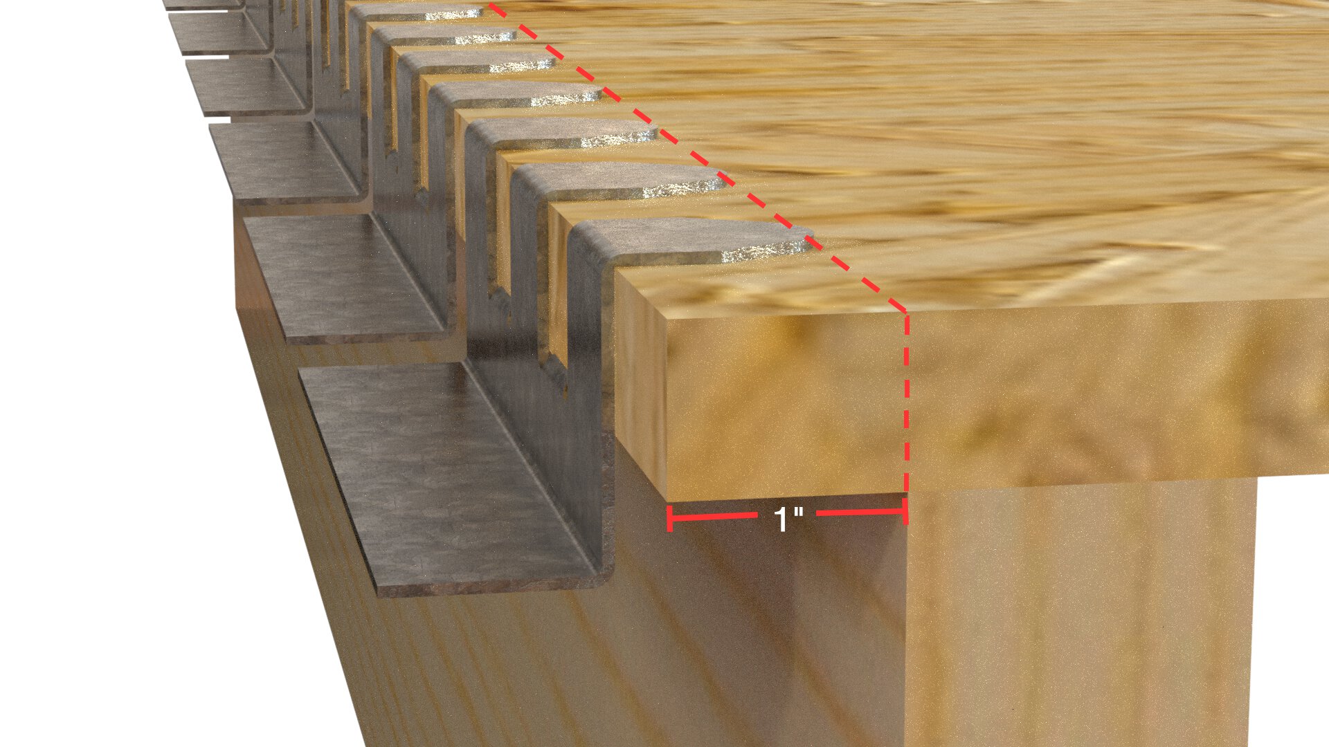
Trace y amplíe la sección recortada hasta la viga siguiente, dejando intacta 1" (2.5 cm) del substrato que sobresale para la fijación de los soportes en P.
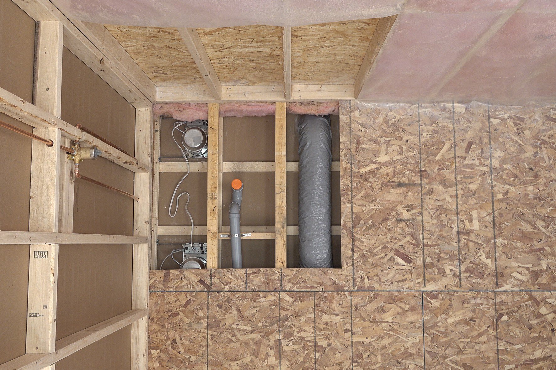
Si el canto cortado ya se encuentra a menos de 1" (2.5 cm), el recorte deberá extenderse hasta la sección contigua.
6

Limpie los cantos del orificio y la parte superior de las vigas, eliminando todo resto de pegamento, astillas, etc.


7

Antes de continuar, compruebe que las dimensiones del orificio sean correctas.
8

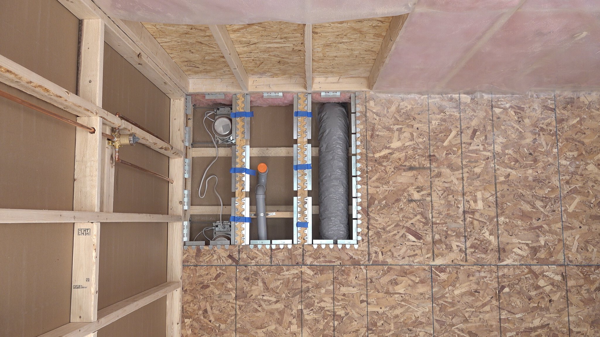
Presente los soportes en seco.

Nota:
Todos los ángulos deben estar apoyados mediante un soporte en P o en J. Es recomendable distribuir y planificar la ubicación de todos los soportes antes de fijarlos en su sitio.

Soportes en P

No corte los soportes en P.
Coloque los soportes en P siguiendo el DIAGRAMA DE COLOCACIÓN DE SOPORTES.
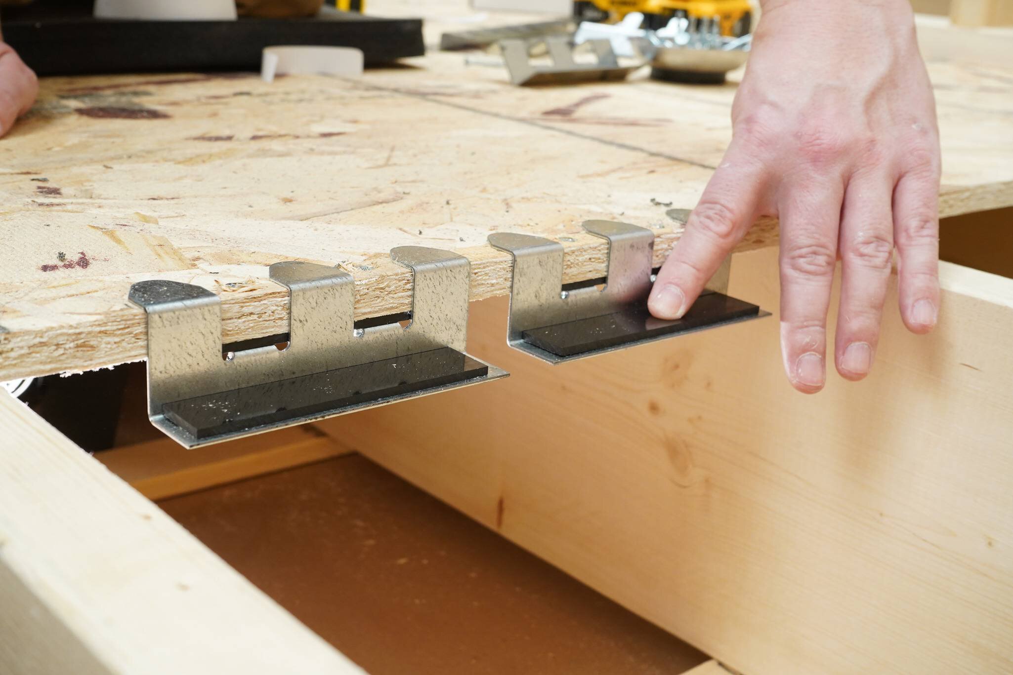
Fije el soporte en P a la placa inferior de la pared con ayuda de una sección de madera y un martillo.
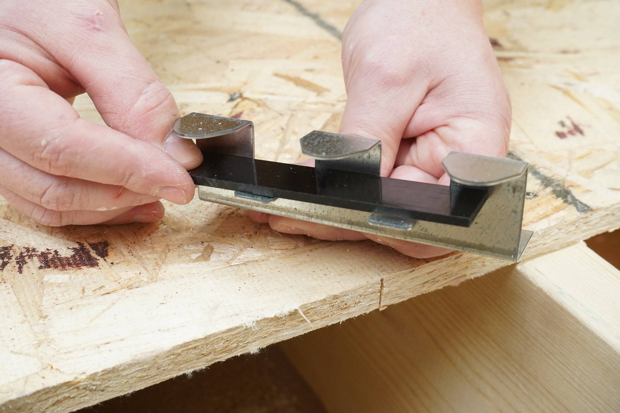
En el caso de los substratos de 5/8" (16 mm), limpie el soporte, coloque calzas en las lengüetas rectangulares e inserte el saliente.

Soportes en J

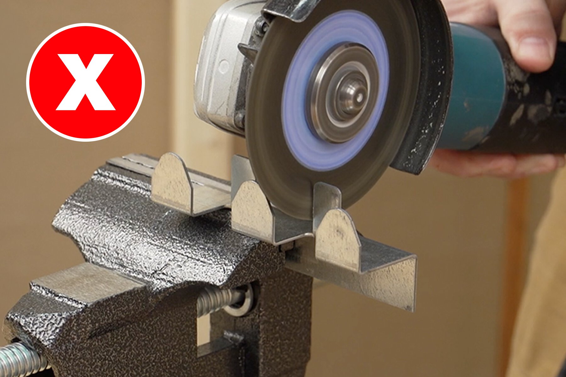
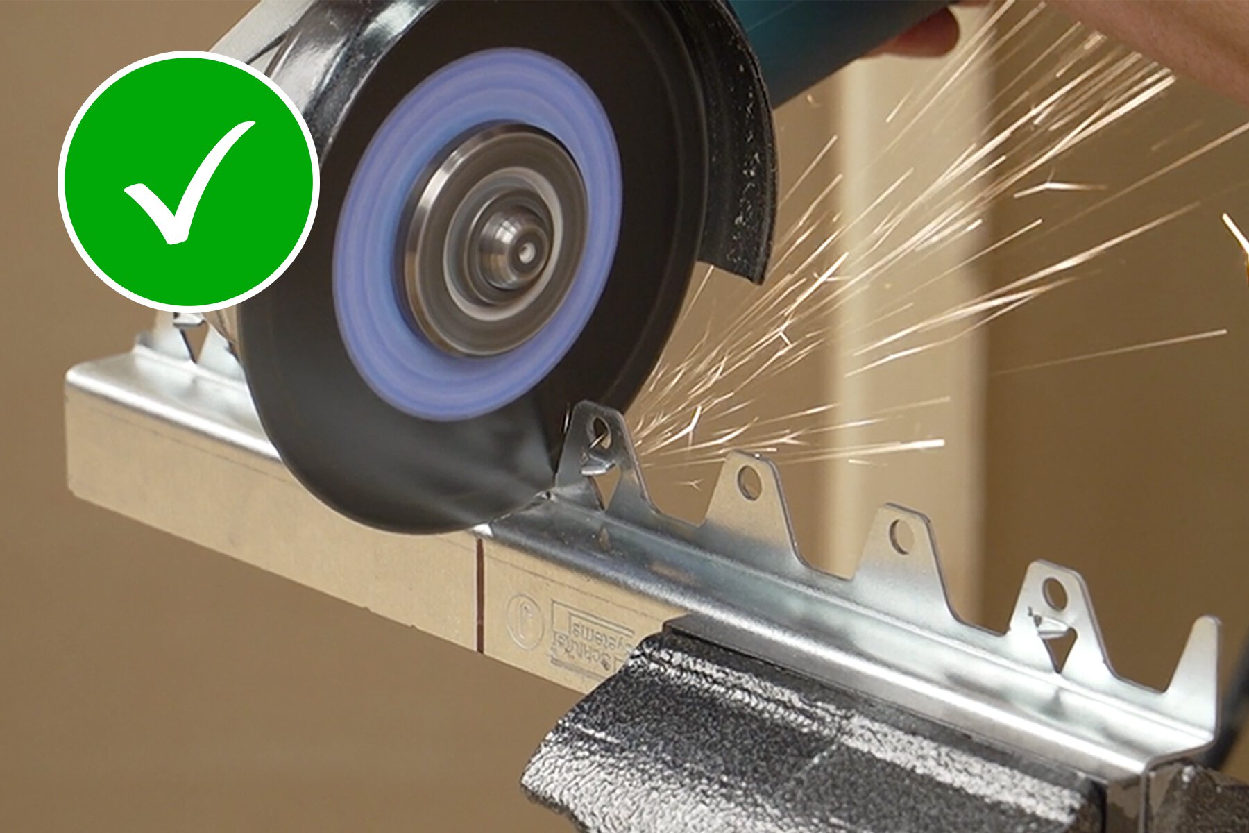
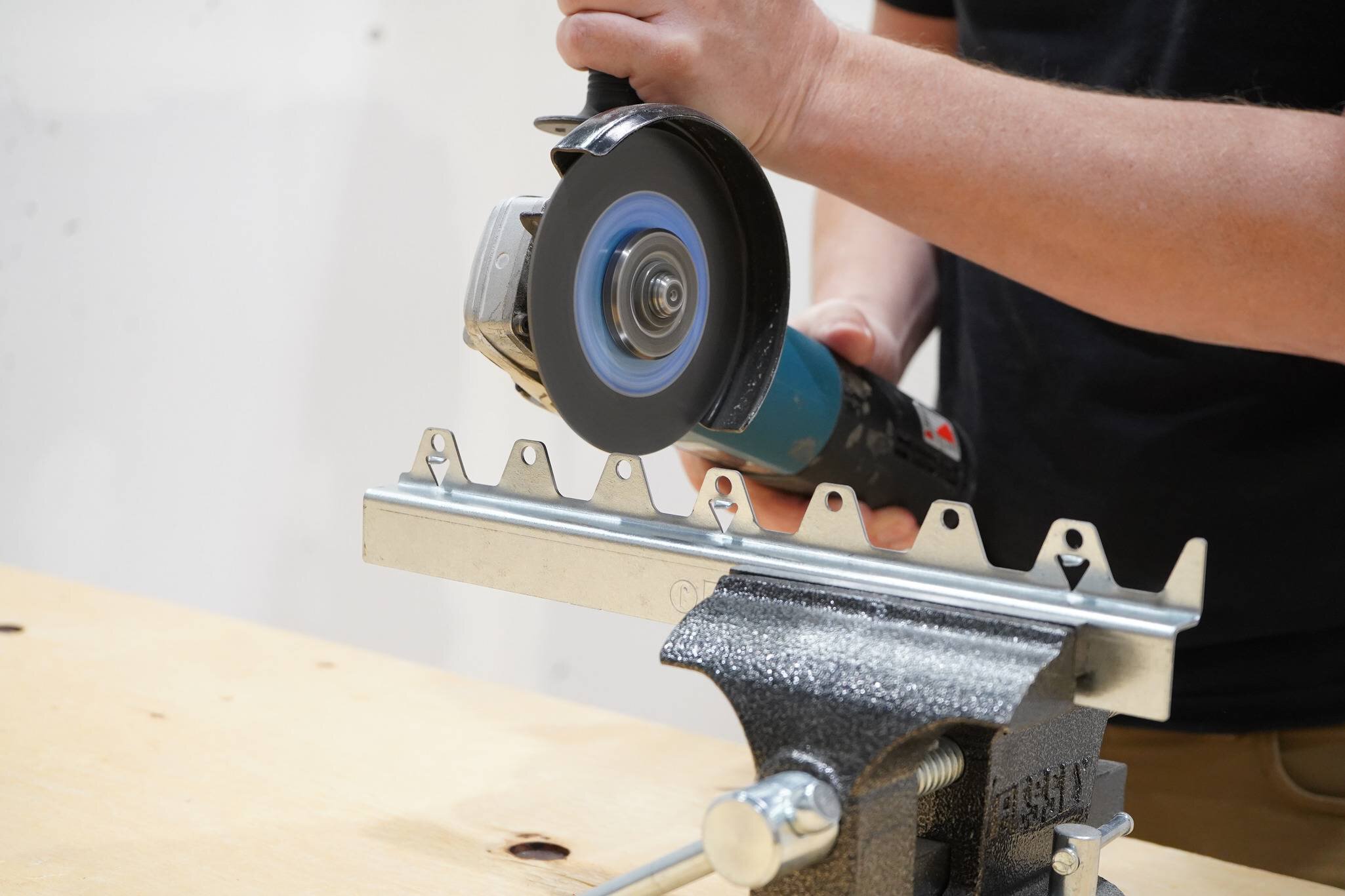
Los soportes en J pueden cortarse a la longitud deseada.
Corte los soportes en J con las herramientas adecuadas (p. ej., una radial angular con Schluter®-PROCUT-TSM).
Es IMPRESCINDIBLE que queden cuatro orificios para tornillos en cada sección cortada que se utilice.
Lay out J-brackets according to the BRACKET PLACEMENT DIAGRAM .
If there is blocking in your floor cavity, use J-brackets on both sides, and ensure corners are supported.
9a

Attach brackets

Attach P-brackets
Pre-drilling recommended (*See Planning step 3. )
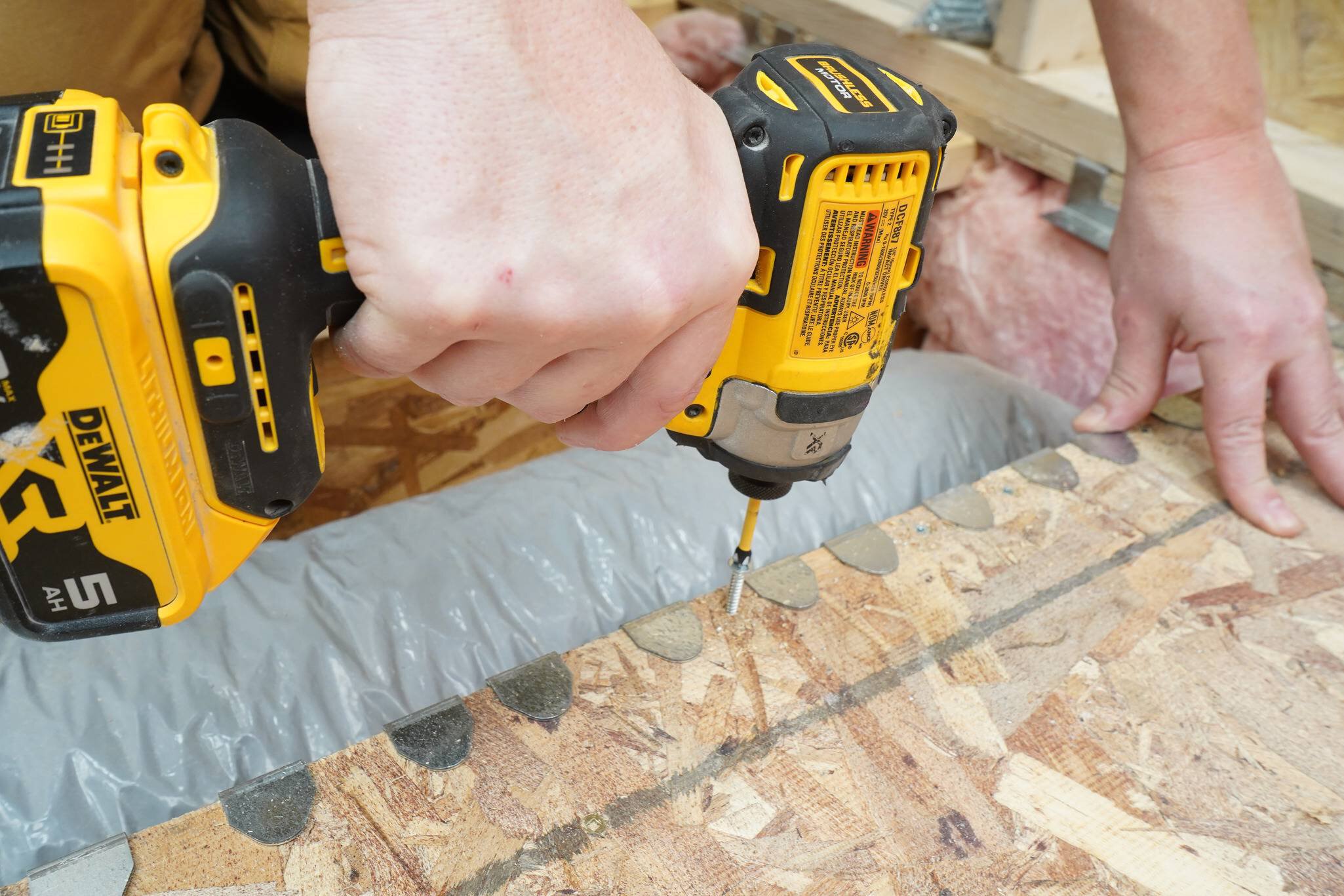
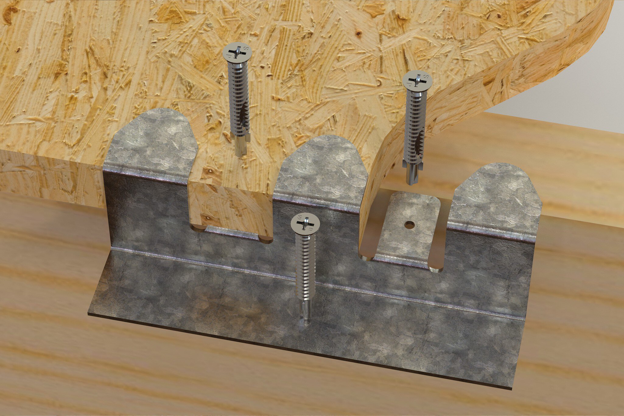
Secure P-brackets to the subfloor with two 1-5/8" (41.2 mm) wood-to-metal screws 1/2" (12.7 mm) from the edge. Screws pass through the subfloor into the rectangular tabs below.
Secure P-brackets to the wall bottom plate using two 2-3/4" (70 mm) wood-to-metal screws 1/2" (12.7 mm) from the edge. Screws pass through the wall’s bottom plate into the center of any of the three top tabs.
Note:
If you choose not to predrill, favor high speed, low pressure until the screw cuts into the metal.
9b

Attach brackets

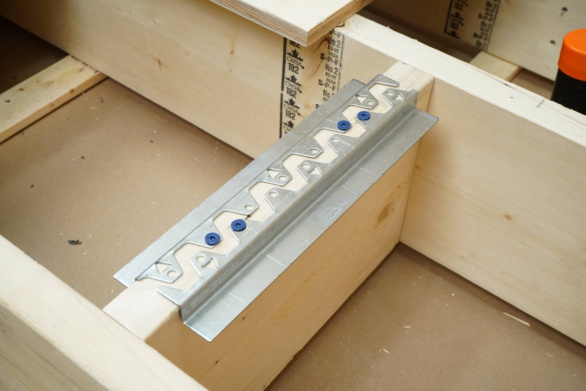
Attach J-brackets
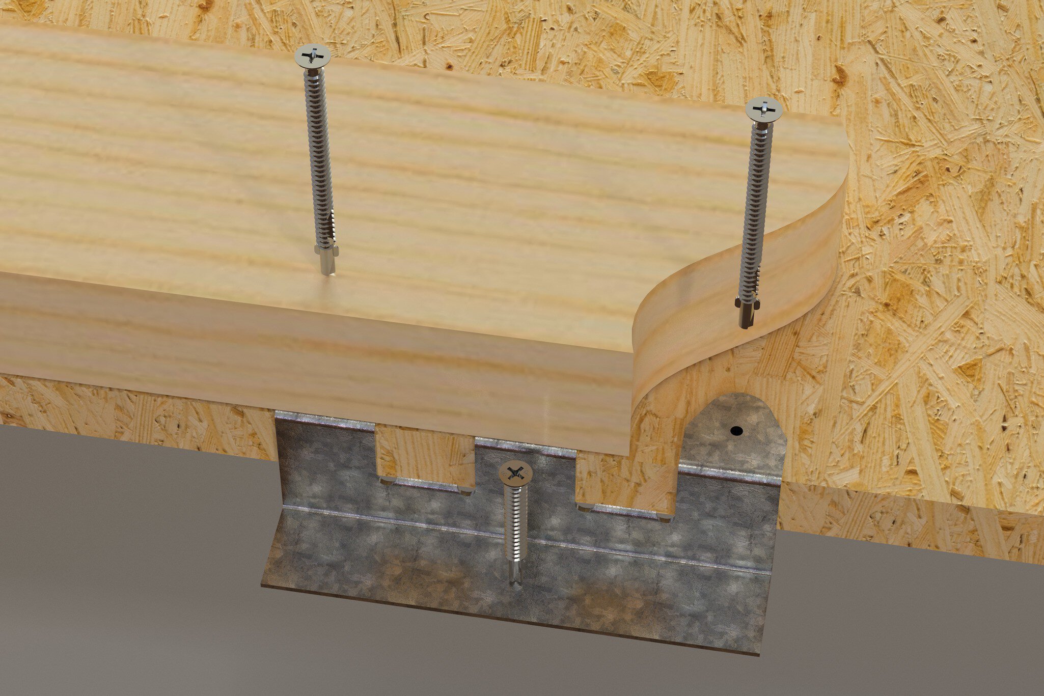
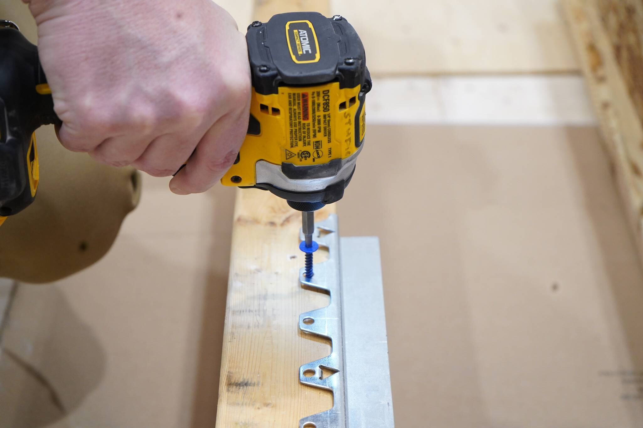
Gently hammer the J-brackets to drive in the tabs, then secure them with two 1 1/8" (29 mm) wood screws, keeping all in-line screws at least 4" (10 cm) apart.
10

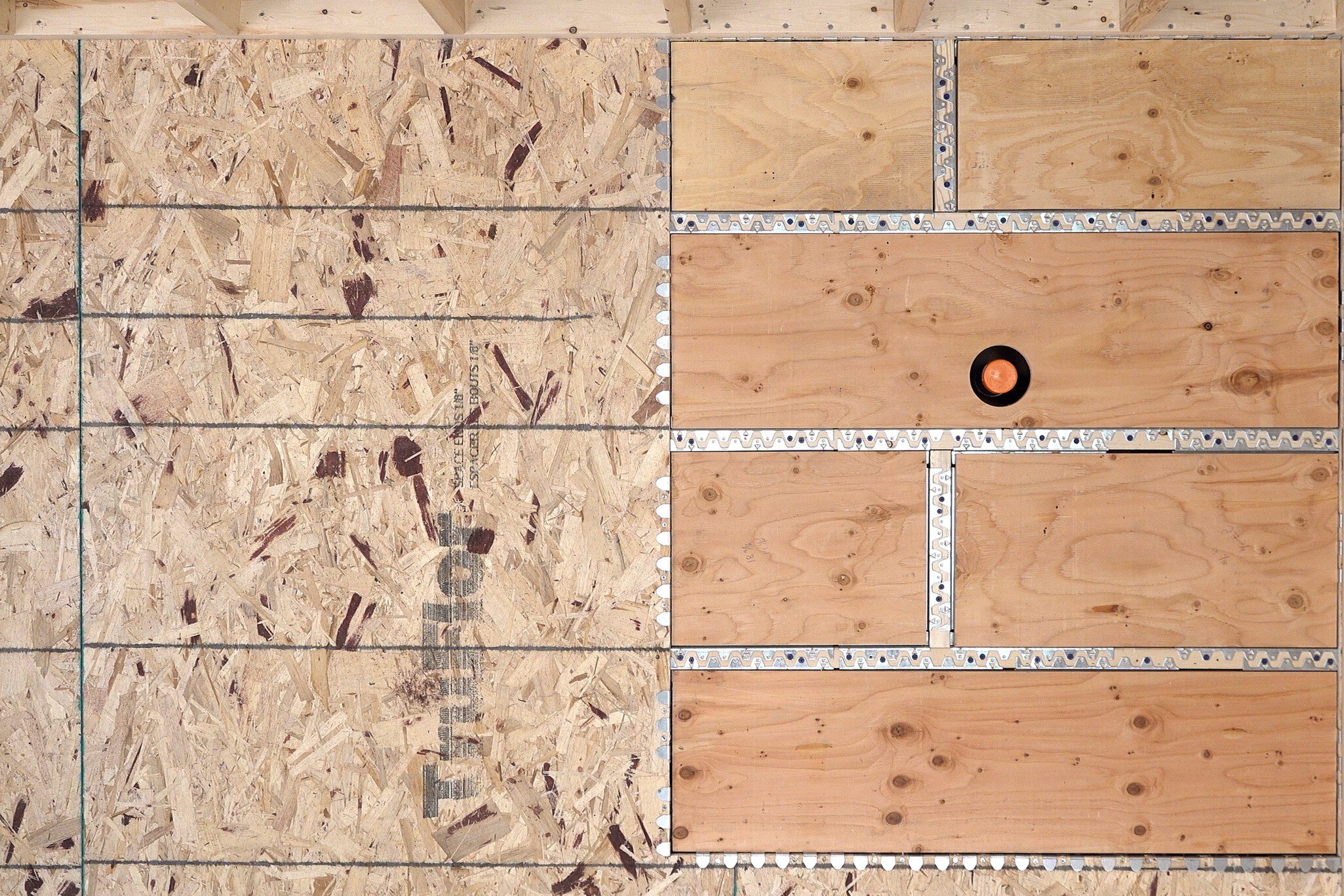
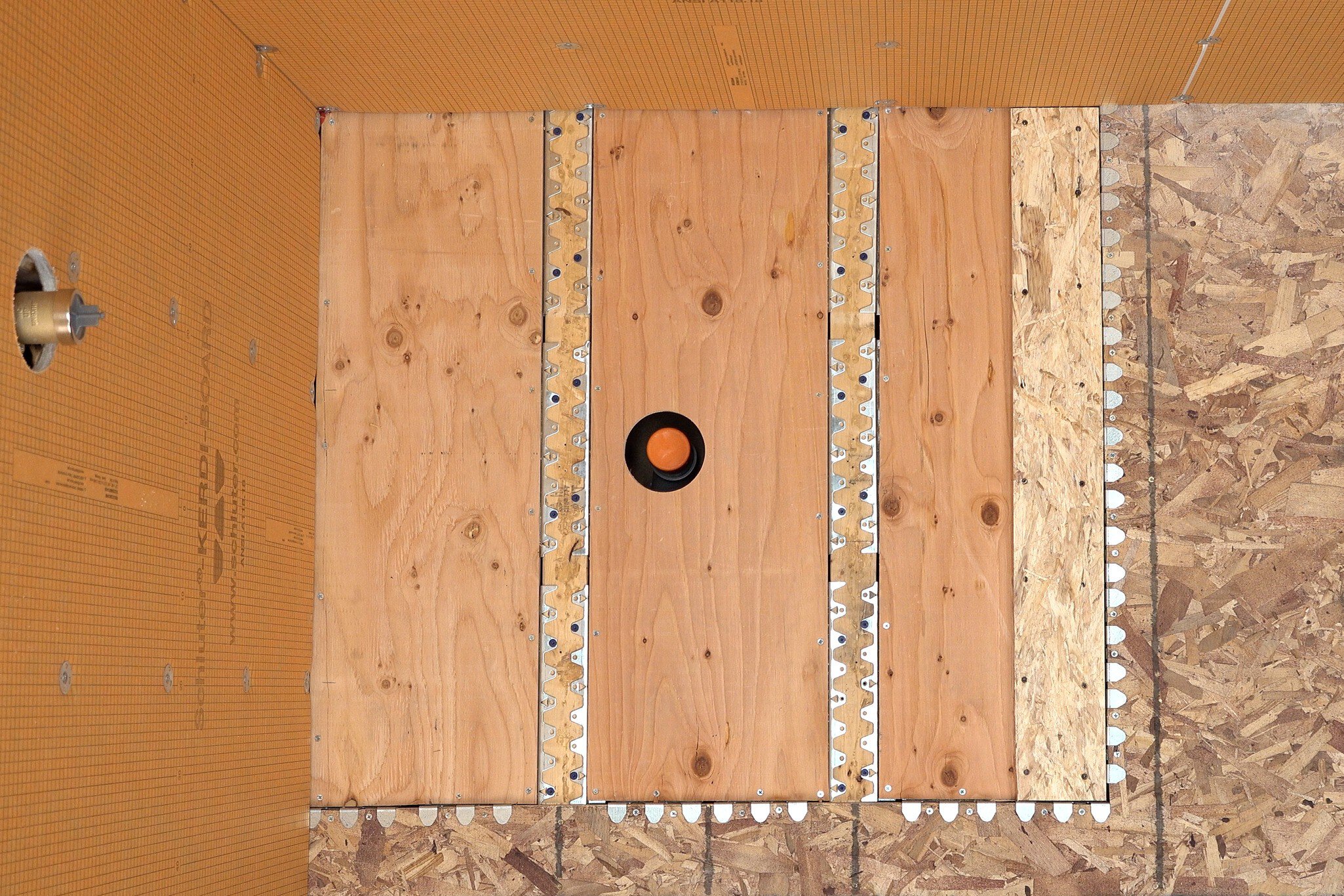
Measure, cut, and place plywood inserts

Inserts shall consist of a single piece of ¾" (19 mm) plywood, and shall be free of holes, damage, or defects, with cleanly cut edges and no blowouts.
Measure each opening between the brackets. Subtract ¼" (6.3 mm) for the Length and Width to allow for an 1/8” (3.2 mm) gap on all sides. 
Manufacturers recommend installing plywood with the face grain perpendicular to supports. FRS testing has verified acceptable performance in all orientations; while perpendicular placement is preferred, panels may be installed in any direction to improve layout flexibility and reduce waste.
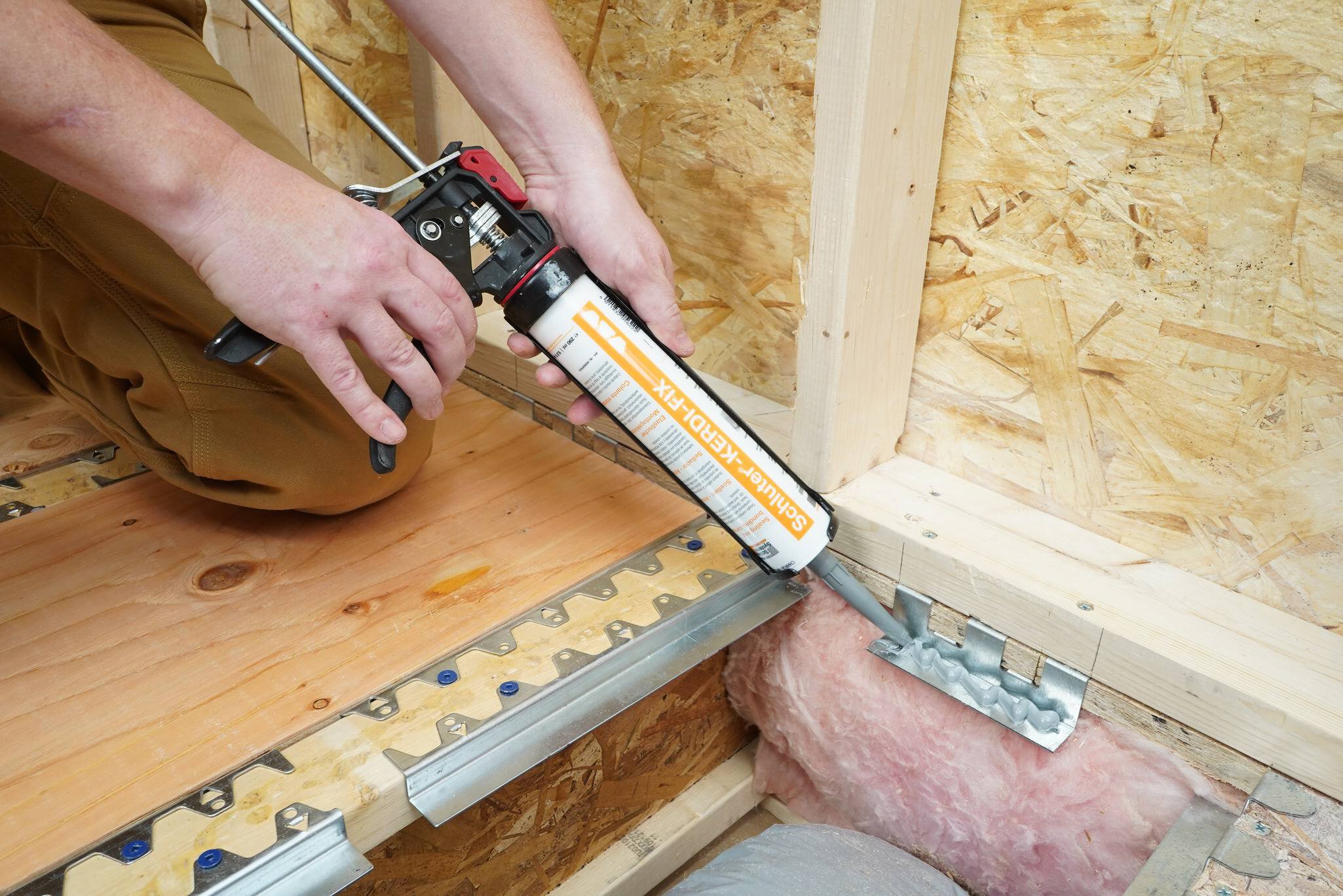
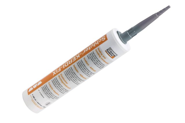
Apply Schluter®-KERDI-FIX or (non-expanding) construction adhesive to all bracket ledges before setting inserts in place.
Note:
OSB may NOT be used for the inserts.
11

Fasten inserts to the brackets

Pre-drilling recommended (*See Planning step 3. )
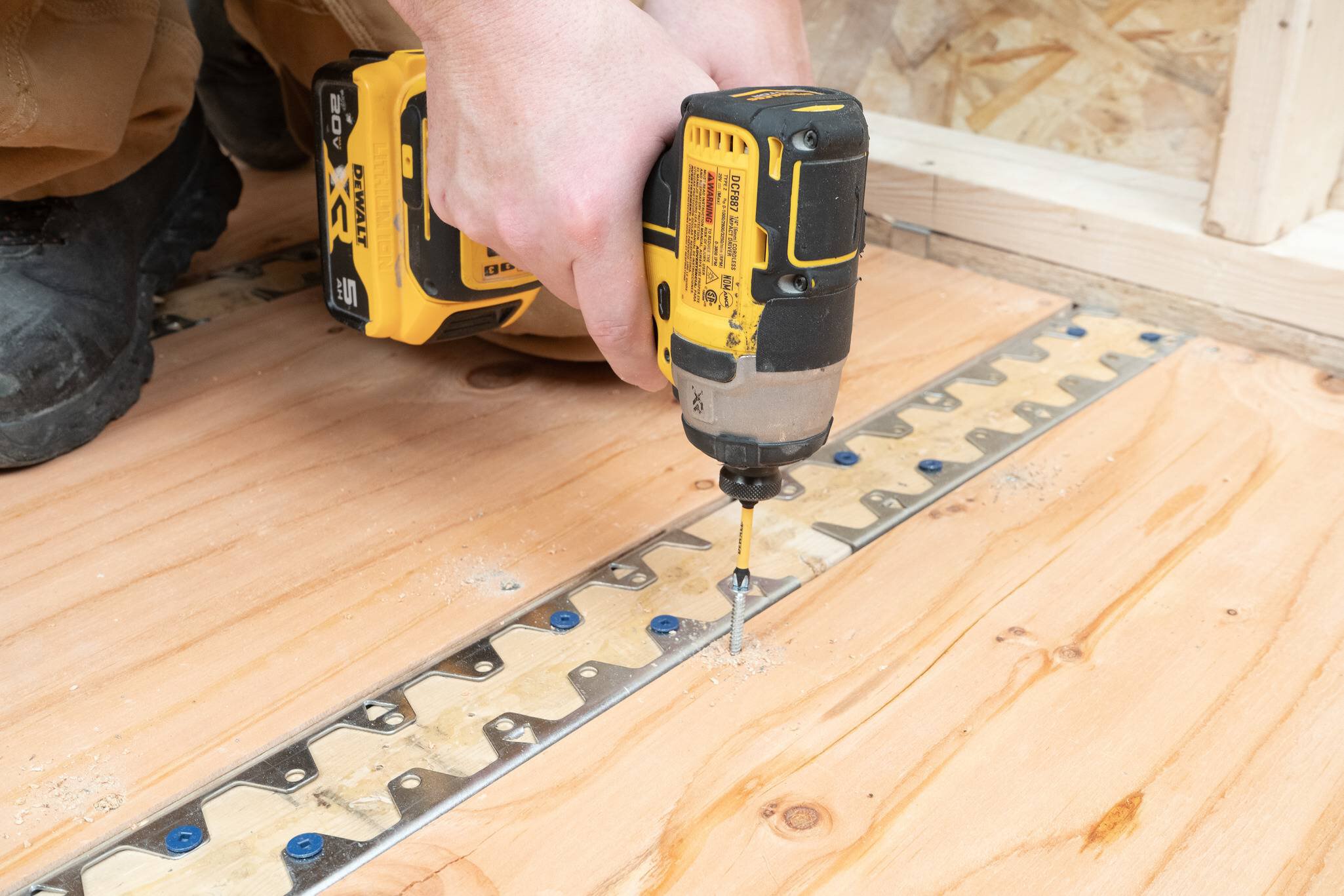
Fasten plywood inserts in place using the provided 1-5/8" (41.2 mm) wood-to-metal screws 1/2" (12.7 mm) from the edge. One screw per P-bracket and two screws, evenly spaced, per J-bracket.
Note:
If you choose not to predrill, favor high speed, low pressure until the screw cuts into the metal.
12

Reinstall/ install wallboard

13

Drill/cut the core hole for the Schluter®-KERDI-DRAIN

Follow all recommendations and instructions for the Schluter®-KERDI-DRAIN to be installed.
Note:
Limit the diameter of the hole to 5" (12.5 cm) maximum to ensure proper support for the tile assembly.
14

Measure, cut, and attach the filler piece

Place the shower tray, then measure and cut a filler piece for the remaining recessed section.
For 3/4" (19 mm) subfloor - use 5/8" (16 mm) plywood or OSB.
For 5/8" (16 mm) subfloor - use 1/2" (12.7 mm) plywood or OSB.
Attach filler pieces.
Treat filler pieces as an additional layer of subfloor sheeting. Follow the manufacturer's recommendation for plywood or OSB and local codes.
Avoid driving screws into bracket ledges (keep 1" (2.5 cm) from the edge).
15

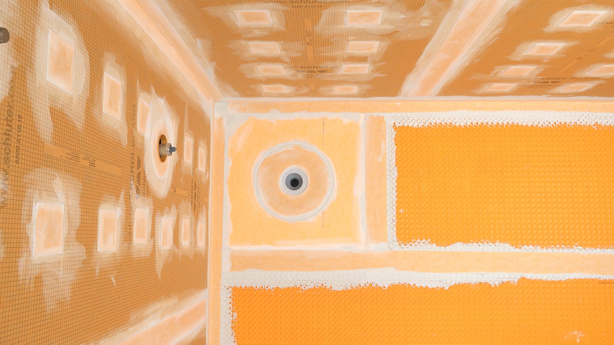
Waterproof the walls

It is recommended to waterproof the walls at this point, then install the tray. The order is up to the installer's discretion.
Refer to the Schluter®-Shower System Installation Handbook for more information.
16

Following the instructions in the Schluter®-Shower System Installation Handbook , check for level and install the tray in the recessed section.

17

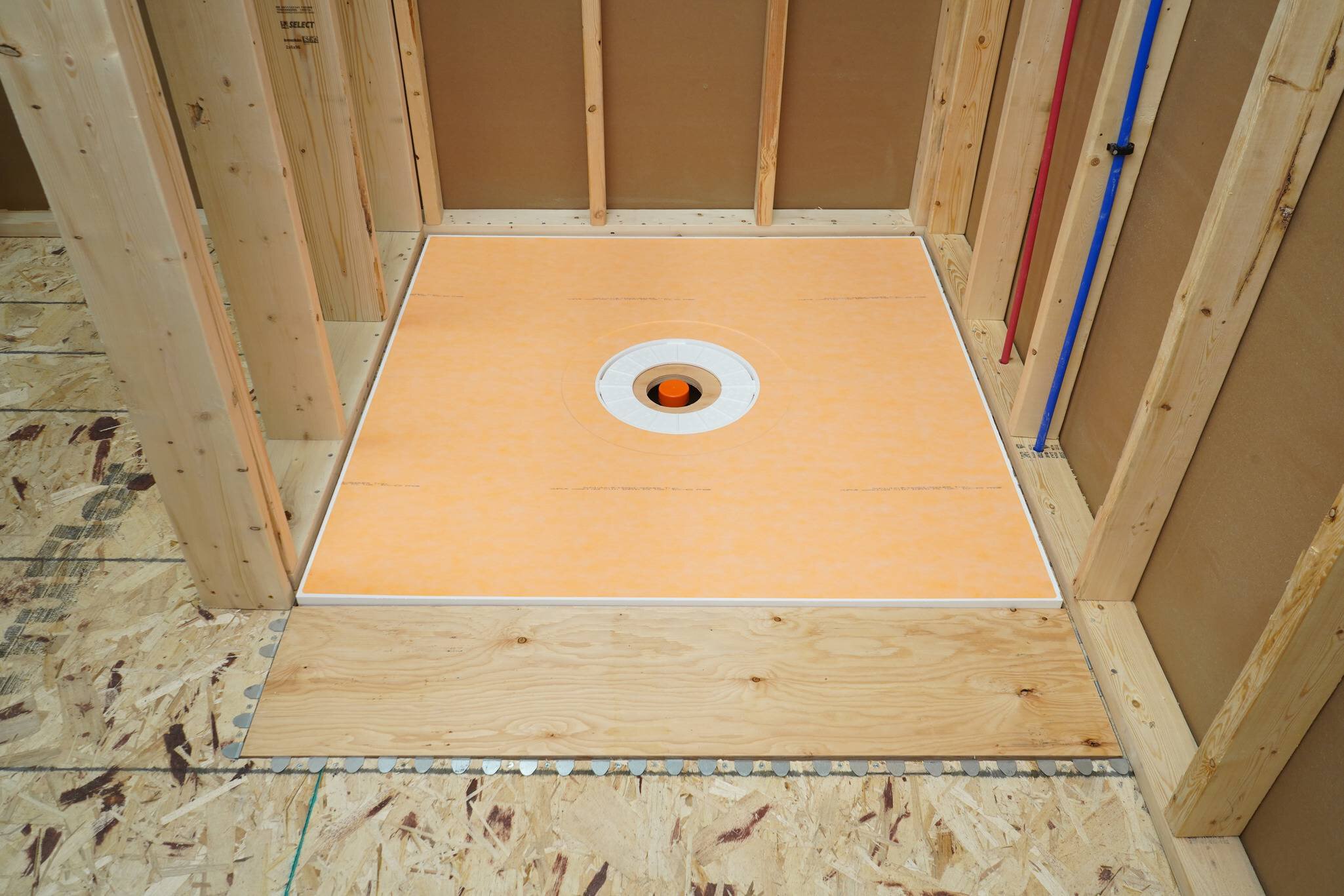
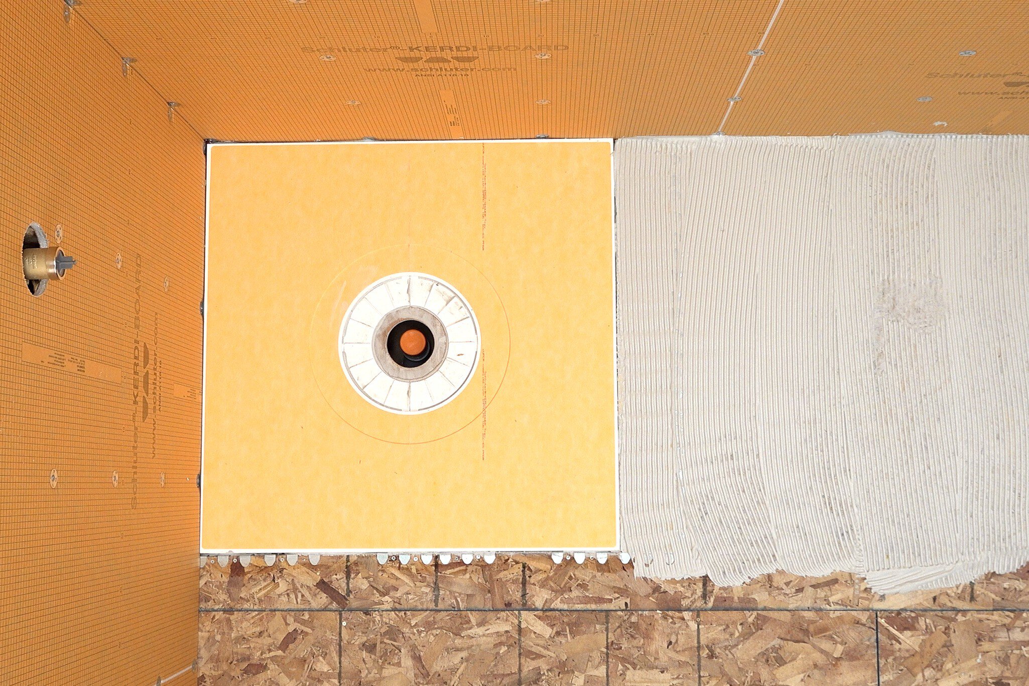
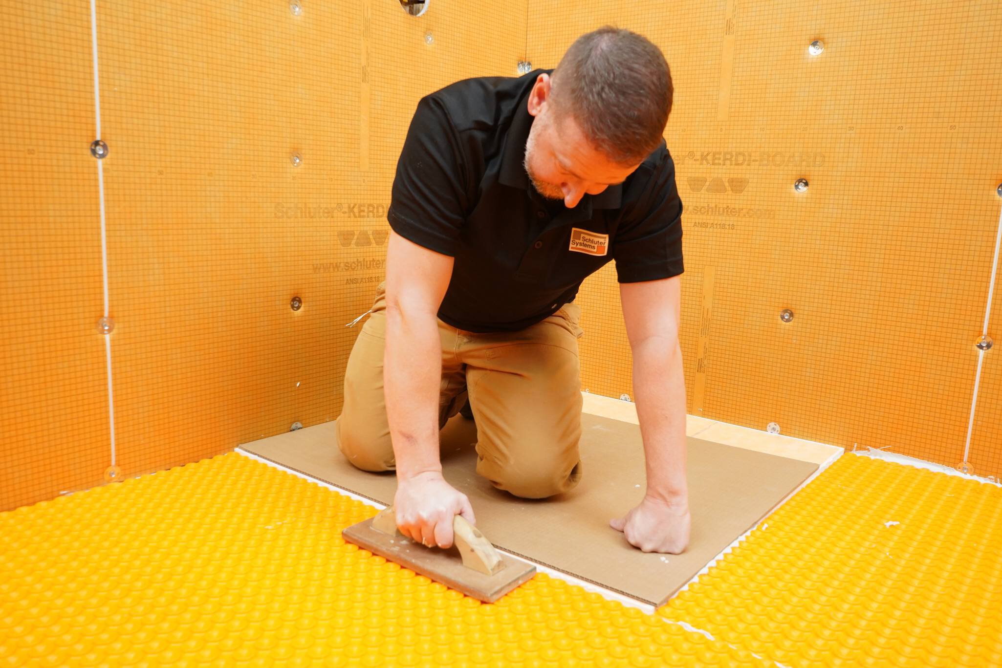
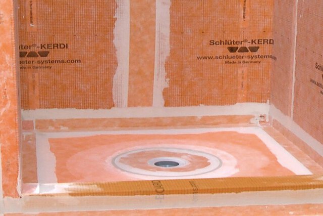
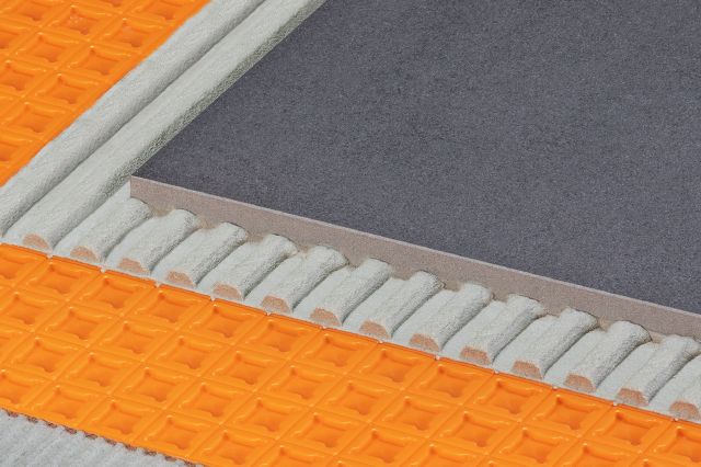
Install Schluter uncoupling membrane (i.e., DITRA, DITRA-HEAT, etc.) flush with the perimeter of the tray.

Use Schluter membranes, patching compound, floor self-leveler, or the appropriate additional underlayment/sheeting as needed.
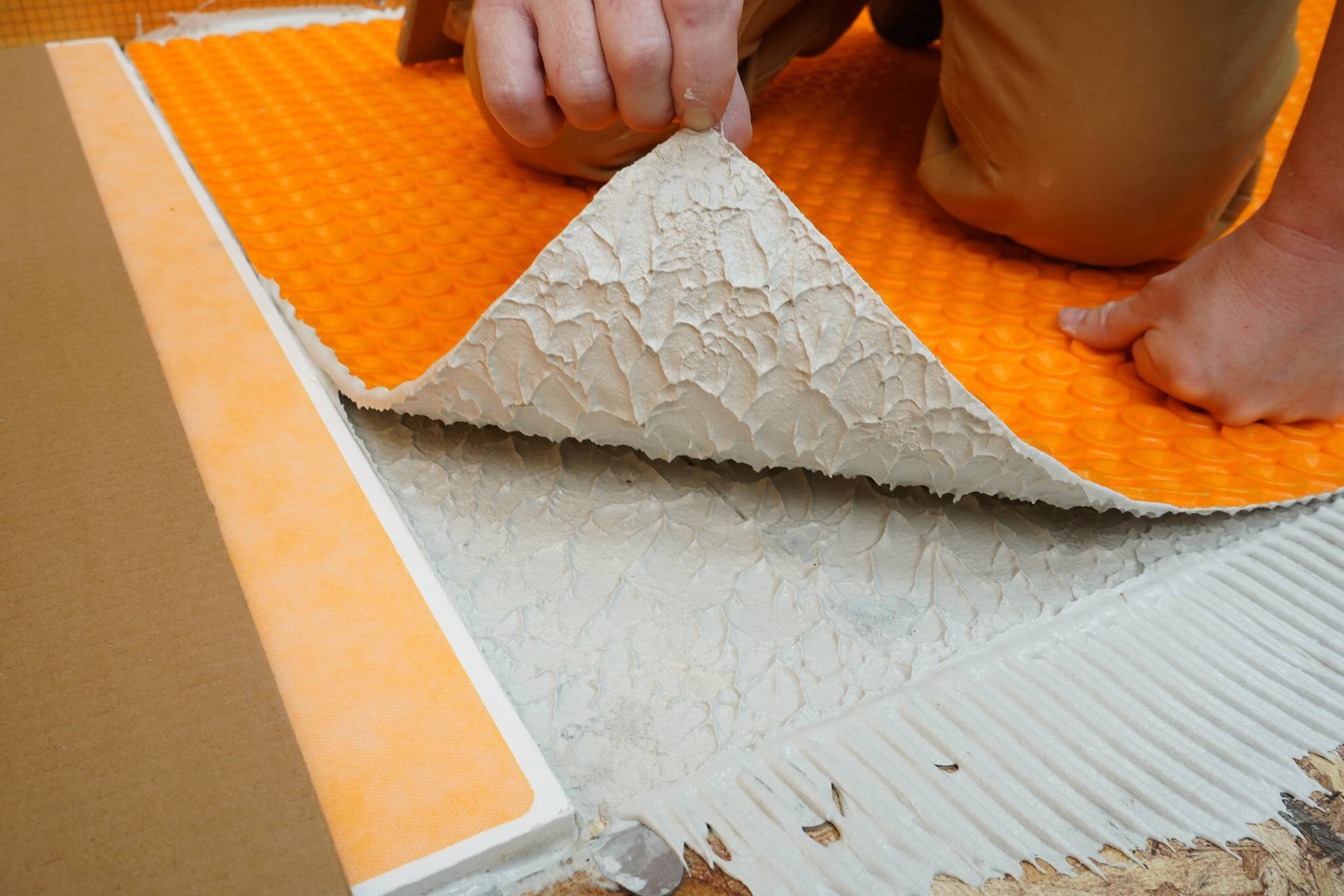
The uncoupling membrane should be installed abutted to and flush with the tray. Take special care to ensure appropriate coverage over bracket tabs.
Reference the COMPONENT THICKNESS table for FRS and common associated component thicknesses.
18

Complete waterproofing

Note:
Industry guidelines recommend waterproofing a minimum of 1 ft (30.5 cm) beyond the shower area for curbless showers.
Follow all requirements outlined in the Schluter®-Shower System Handbook.
Because wet areas and dry areas are not clearly defined in curbless showers, Schluter recommends that the bathroom be sufficiently protected against water and moisture. Use the appropriate Schluter waterproofing products in all floor areas subject to water exposure (i.e., wet area and drying area).
Seams and floor-to-wall connections shall be sealed with KERDI-BAND.
19

Perform Water Test (Strongly Recommended)

Before setting tile to verify a successful installation:
Wait a minimum of 24 hours after the membrane installation is complete to allow for final set of thin-set mortar and ensure waterproof performance of seams and connections.
Refer to local plumbing codes for any specific requirements in your area.
For curbless showers, a temporary dam must be provided at the threshold to perform the water test.

CAPILLARY BREAK RECOMMENDATION

Consider installing a capillary break to reduce the risk of moisture migration from the curbless shower to the drying area. Refer to the TCNA Handbook for Ceramic, Glass, and Stone Tile Installation for more information.

Schluter®-KERDI-DRAIN

Schluter®-
KERDI-DRAIN

Point drain with integrated bonding flange

Schluter®-KERDI-SHOWER-T/-TS/-TT

Schluter®-
KERDI-SHOWER-T/-TS/-TT

Prefabricated sloped shower tray

Schluter®-KERDI

Schluter®-
KERDI

Bonded waterproofing and vapor-retardant membrane

Schluter®-KERDI-FIX

Schluter®-
KERDI-FIX

Single-component sealing and bonding compound

Schluter®-DITRA & DITRA-XL

Schluter®-
DITRA & DITRA-XL

Uncoupling and waterproofing membrane

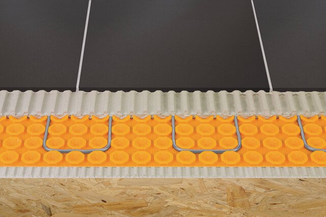
Schluter®-DITRA-HEAT

Schluter®-
DITRA-HEAT

Uncoupling membrane for DITRA-HEAT-E-HK electric floor heating cables